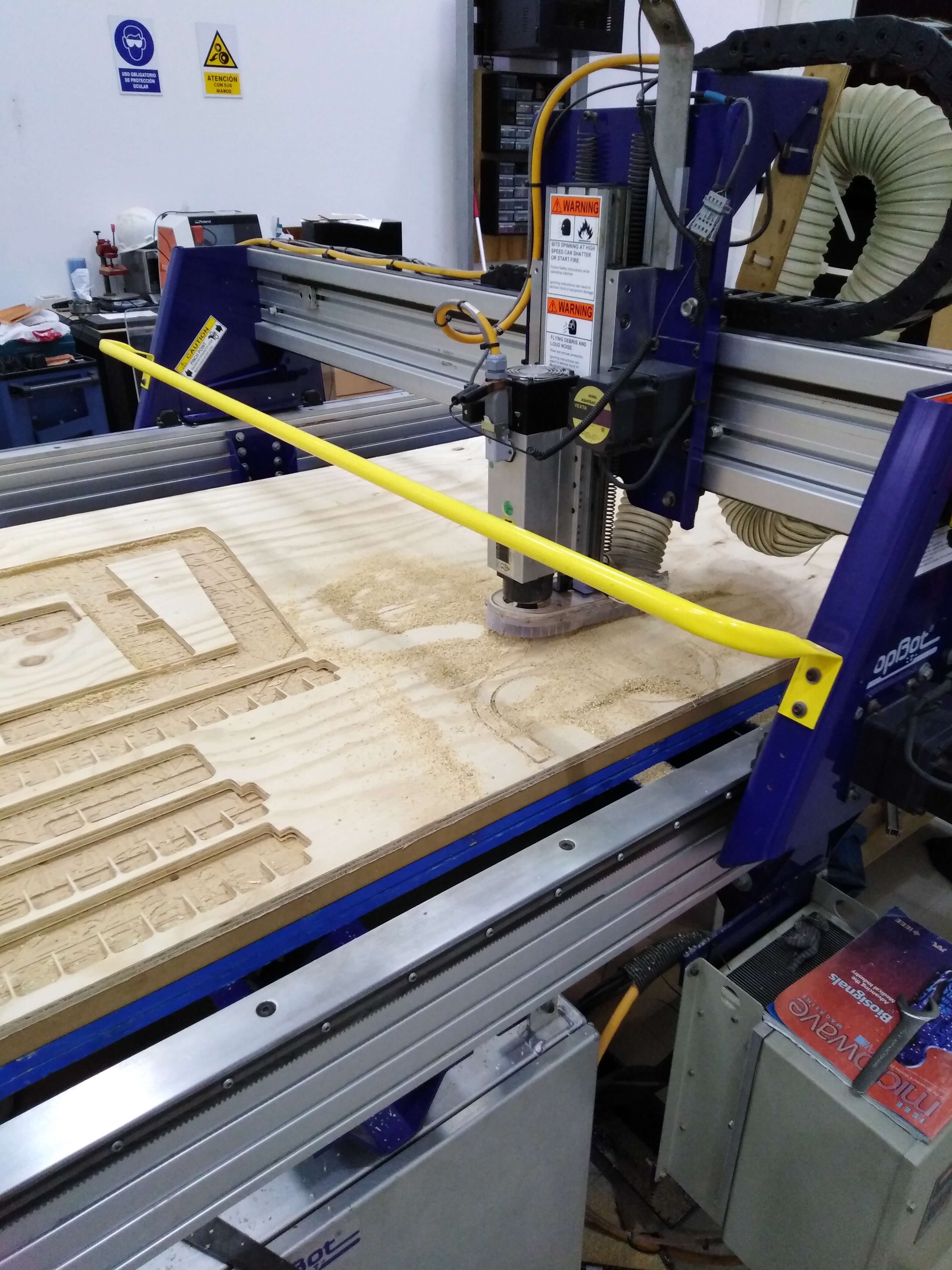
Test equipment
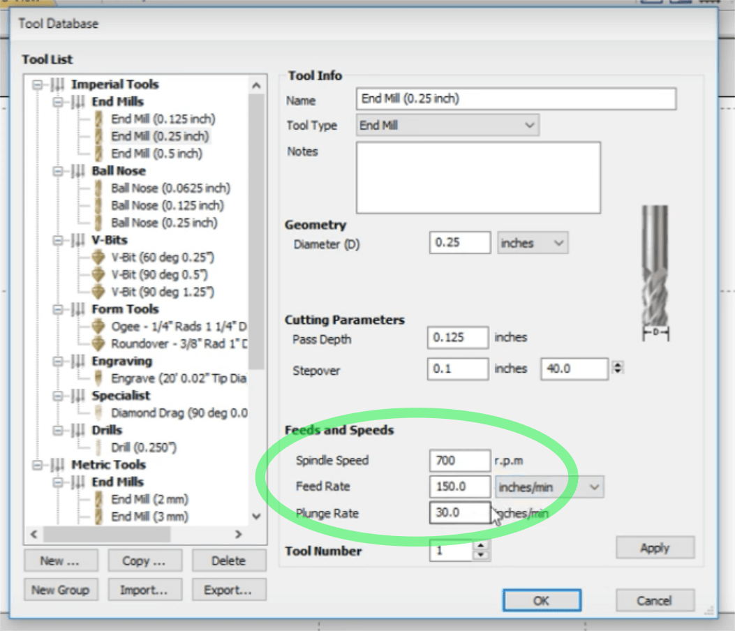
For this week we use the ShopBot PRSalpha which has a capacity of 2.4 x 1.2 m. One of the most important parameters is to determine the spindle speed, which in turn depends of the material to be machined, the diameter of the tool and the feed rate, is important because it coul damage the tool. We use plywood with 15 mm depth, and a end mill with 1/4", so we starte use a spindle speed of 700 rpm and a feed rate of 150 inches/min.feed rate of 150 inches/min. Use this page for calculating a first aproach.
After using these parameters in the CNC machine, they were found to work well:
- Initial setup parameters:
- Spindle speed: 700 rpm
- Feed rate: 150 inches/min
Set up and press fit test
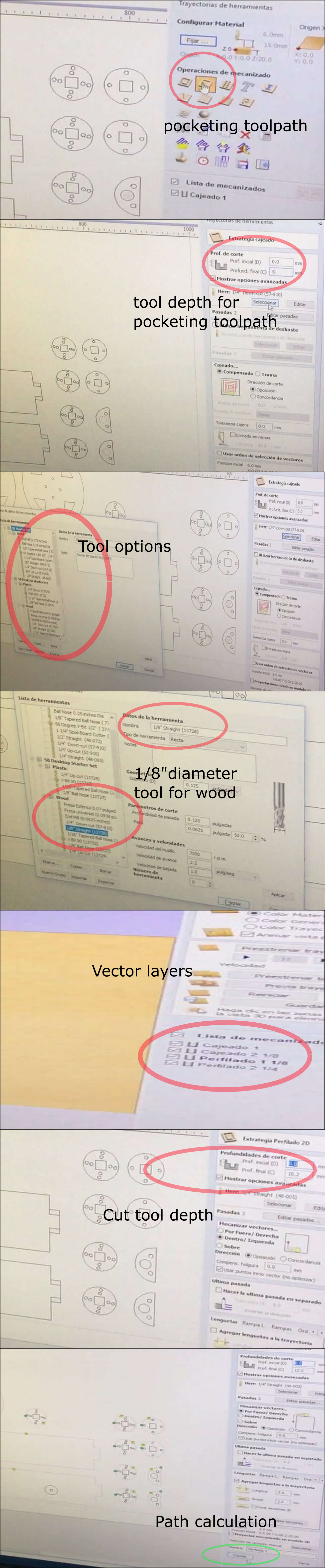
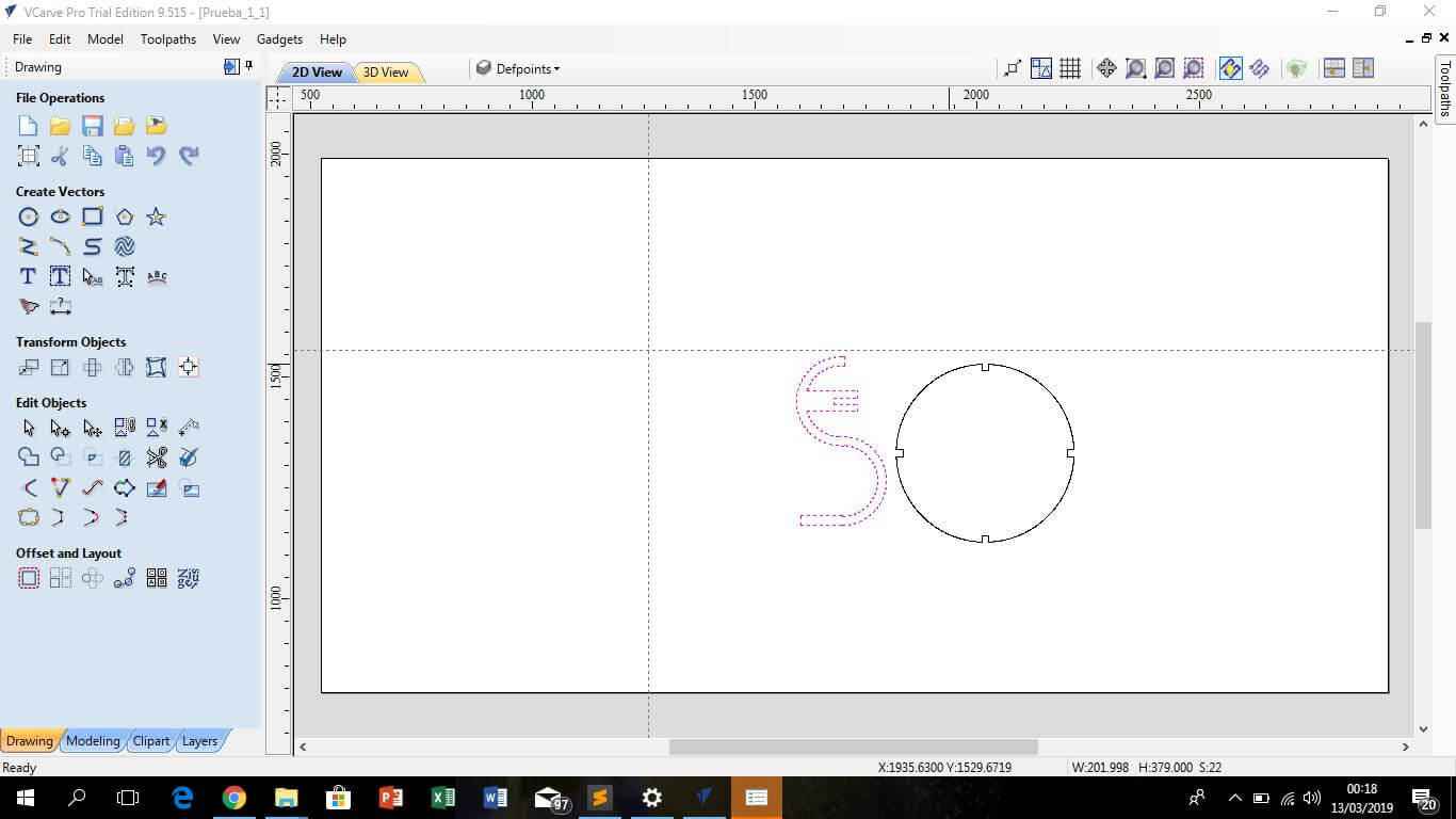
The VCarve Pro is the software for control the CNC. Once we have the .DXF drawing (generated from a 3D model), open in VCarve Pro for defining the features of the machining upon the drawing lines.
In a general way, I follow this steps for setting up the CNC:
-
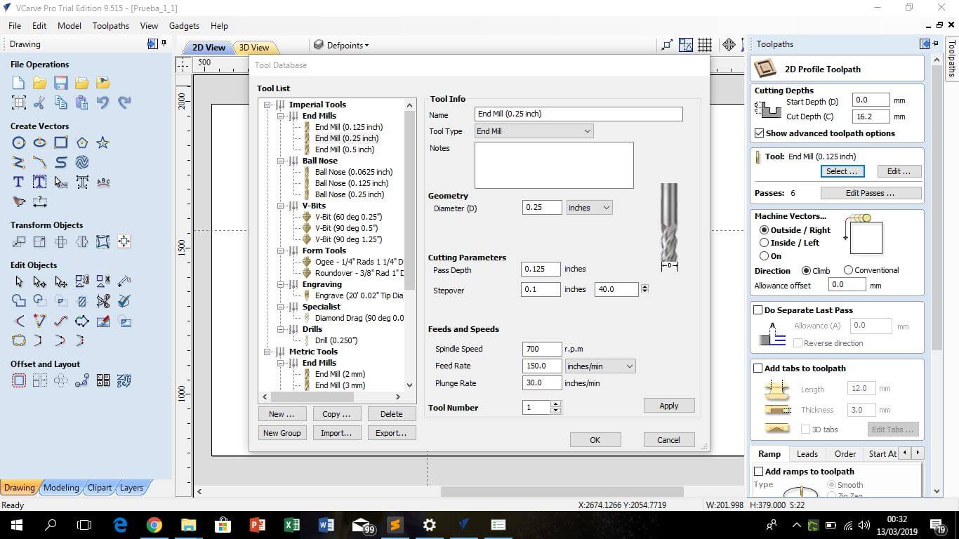
Select the toolpath, profile toolpath to cut around or along a vector or pocketing toolpath just to generate wear on the surface. Here is essential the assign the correct final depth of the mill, in the case of cutting, is recommendable added a little bit more depth than the material thickness, in my case I use a 15 mm playwood, and used a depth of 16.2 mm; in the case of pocketing toolpath the depth needs to be exact.
-
The next step is to select the correct endmill, I use 1/8 "and 1/4". The first one for cut, drill and pocketing, the second one only for drill 1/4 "specific holes. (Here is possible to edit the Spindle speed and the Feed rate)
So, if possible create a set of vector layers, every one with his own characteristics as depth or tool diameter.
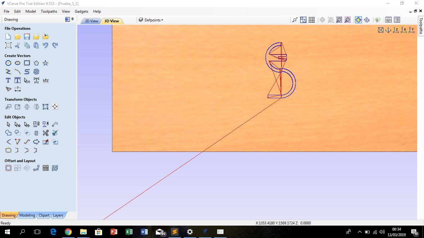
Finally, the program calculates the path that is going to be followed by the tool, respecting the order of the vector layers. Every layer has his own features, like using a specific endmill o cut depth for a particular line or vector.
-
Resume: setup for press fit test
Material thickness: 15 mm
Depth for profile toolpath: 16.2mm
Depth for pocketing toolpath: 5 mm
Endmill used: 1/8" for cut, drill and pocketing, 1/4" for cut, drill and pocketing
Vector layers:
1. 1/8" pocketing
2. 1/4" pocketing
3. 1/8" profiling
4. 1/4" profiling,
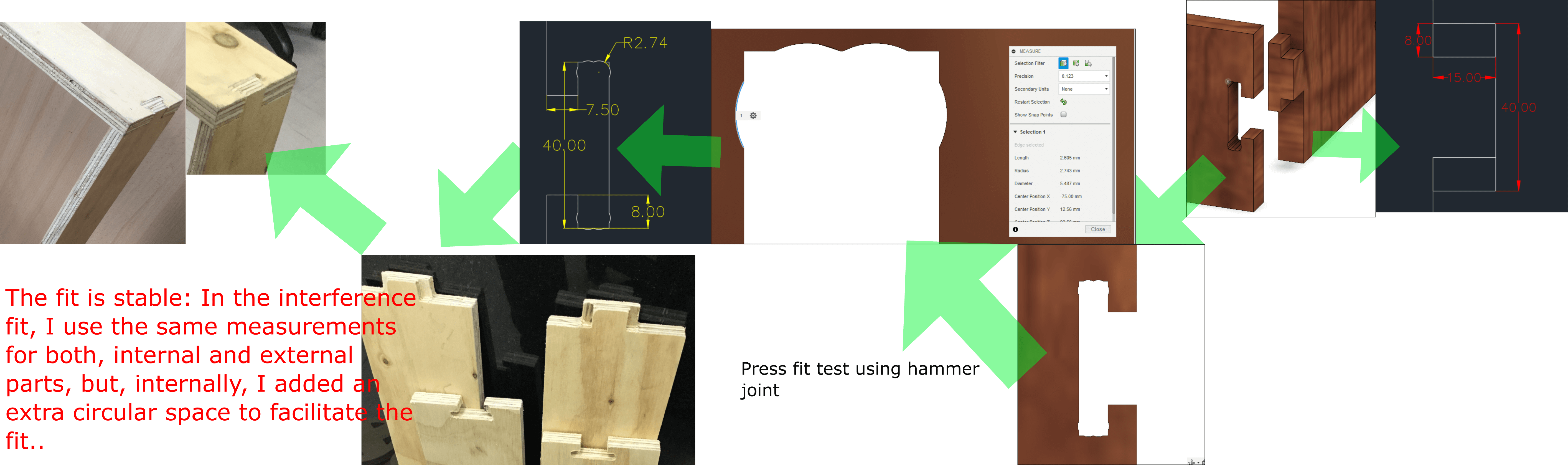
Press fit test
For the press fit test I use a hammer joint, for profiling and pocketing use both, 1/8" and 1/4" endmill. Both the input and output connection elements use the same measurements, but on the inside I added additional circular spaces in the vertices to facilitate the entry of the external connection parts.
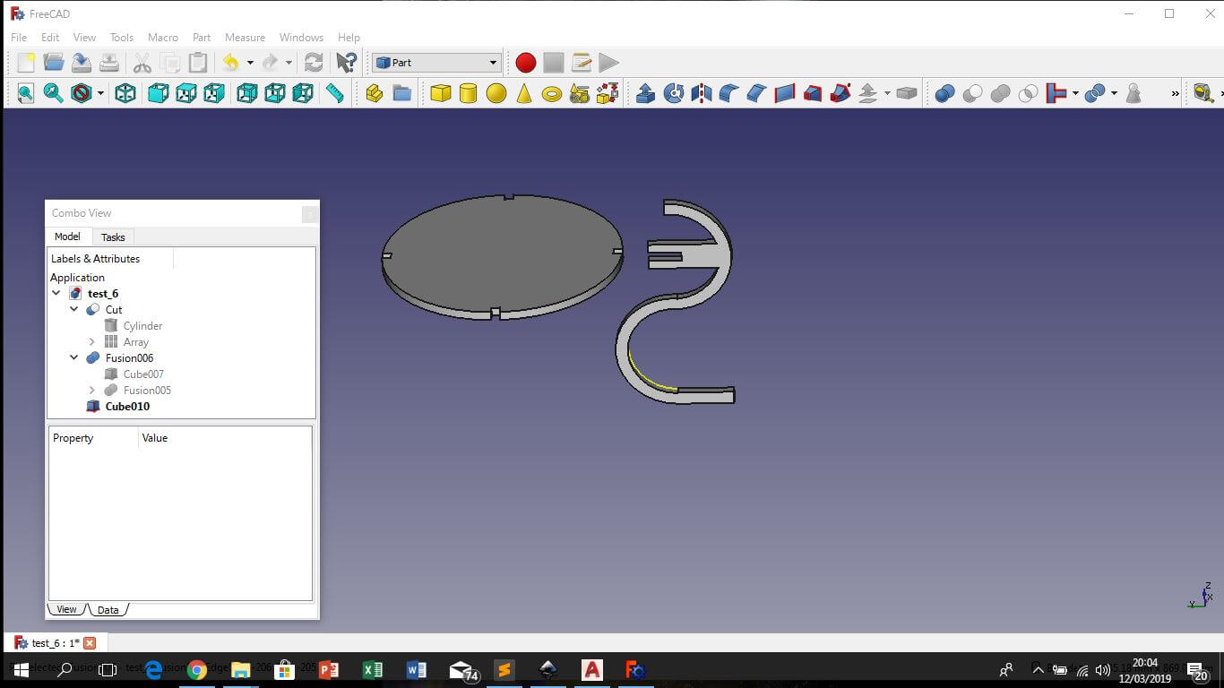
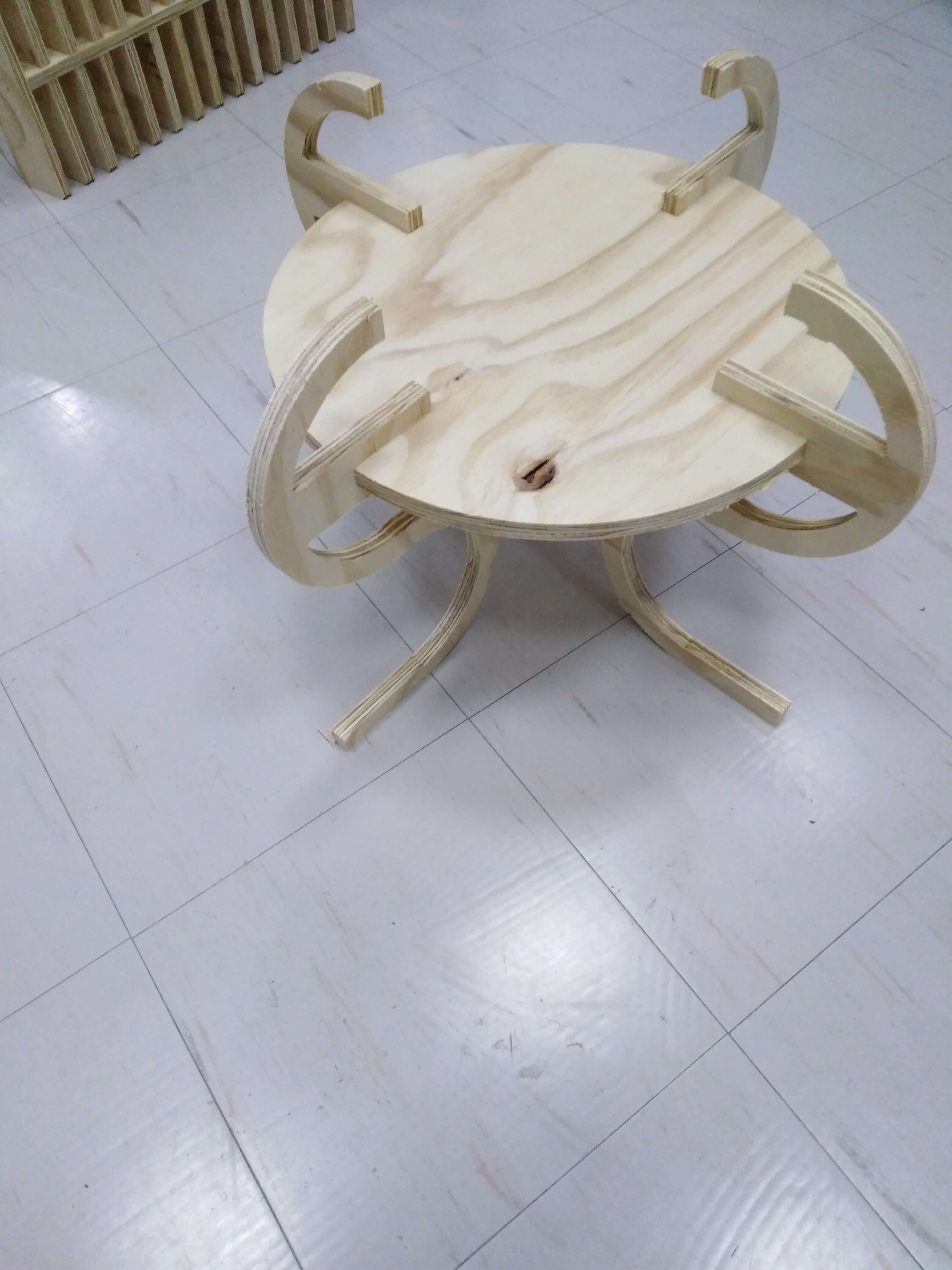
Make something big
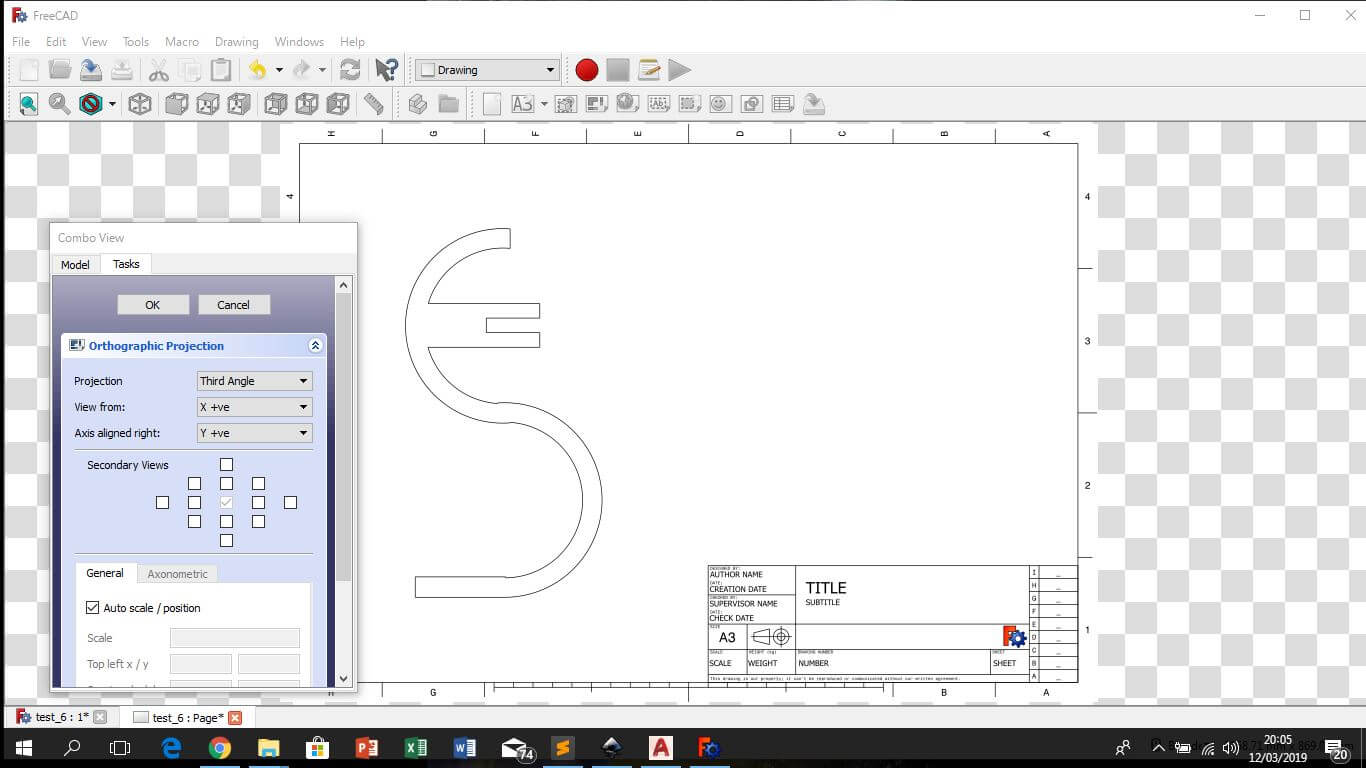
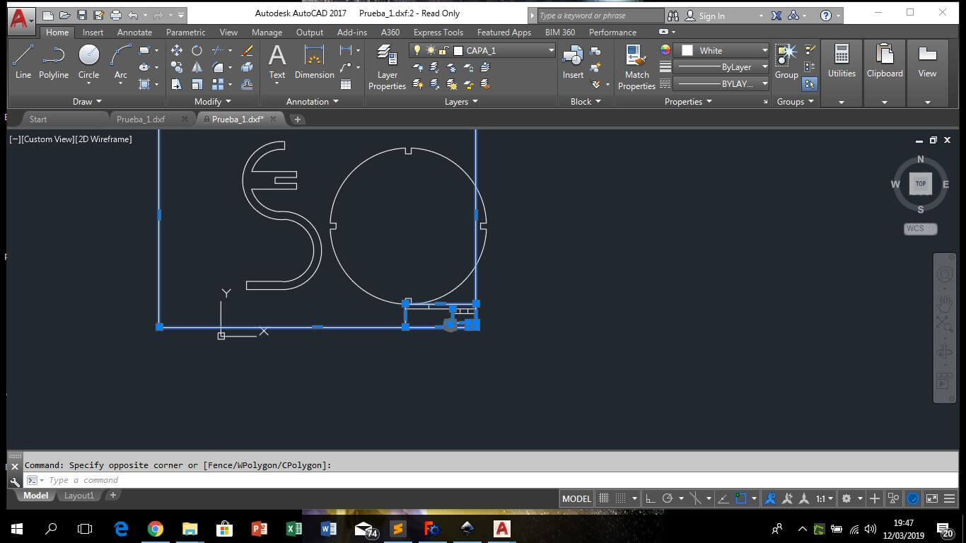
For this week assignment I use Freecad and design a simple table. For the design, I insert a few cubes and cylinders and modify his dimensions, then use the cut and fusion tools for subtracting and adding 3d surfaces to generate final shapes (in "part" view). Once the model was finished, go to the "drawing" view for capture de 2d top view, then select an appropriate landscape and looking for the scale of the drawing to be 1:1, then save as a .DXF file. Then I openned in AutoCad for edit the .DXF file because the drawing was exported with his frame. I like to use FreeCad, but it´s a little tricky and is possible to losse a lot of time traying to understand it, if you are a novel.
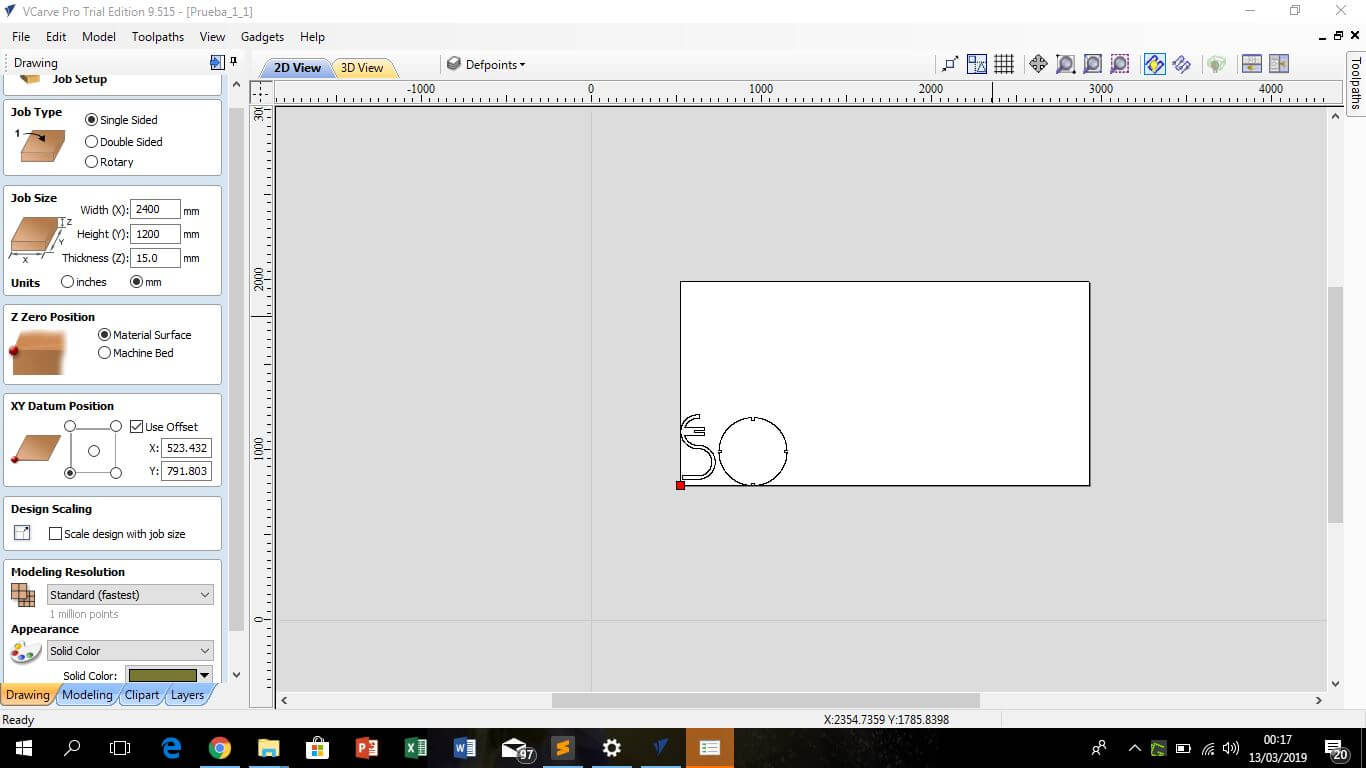
For control de Shopbot use VCarve Pro. This software support .DXF files, so in the Job Setup define the dimensions of the board and place the 0,0 point. Then in file operations is posible to post edit your drawing and place it in somewhere in the plywood board. It is important to consider the minimum distance between drawing and drawing to take better advantage of the area of the table, this is a function of the width of the tool, then you have to consider something more than twice the diameter of the tool. In the toolpath the machine is set so that first mark on the table the points where the screws will be placed to secure the work area. Then select the cutting option, select the tool and the tool parámeters and calculate the work and if everything is ok send to cut.
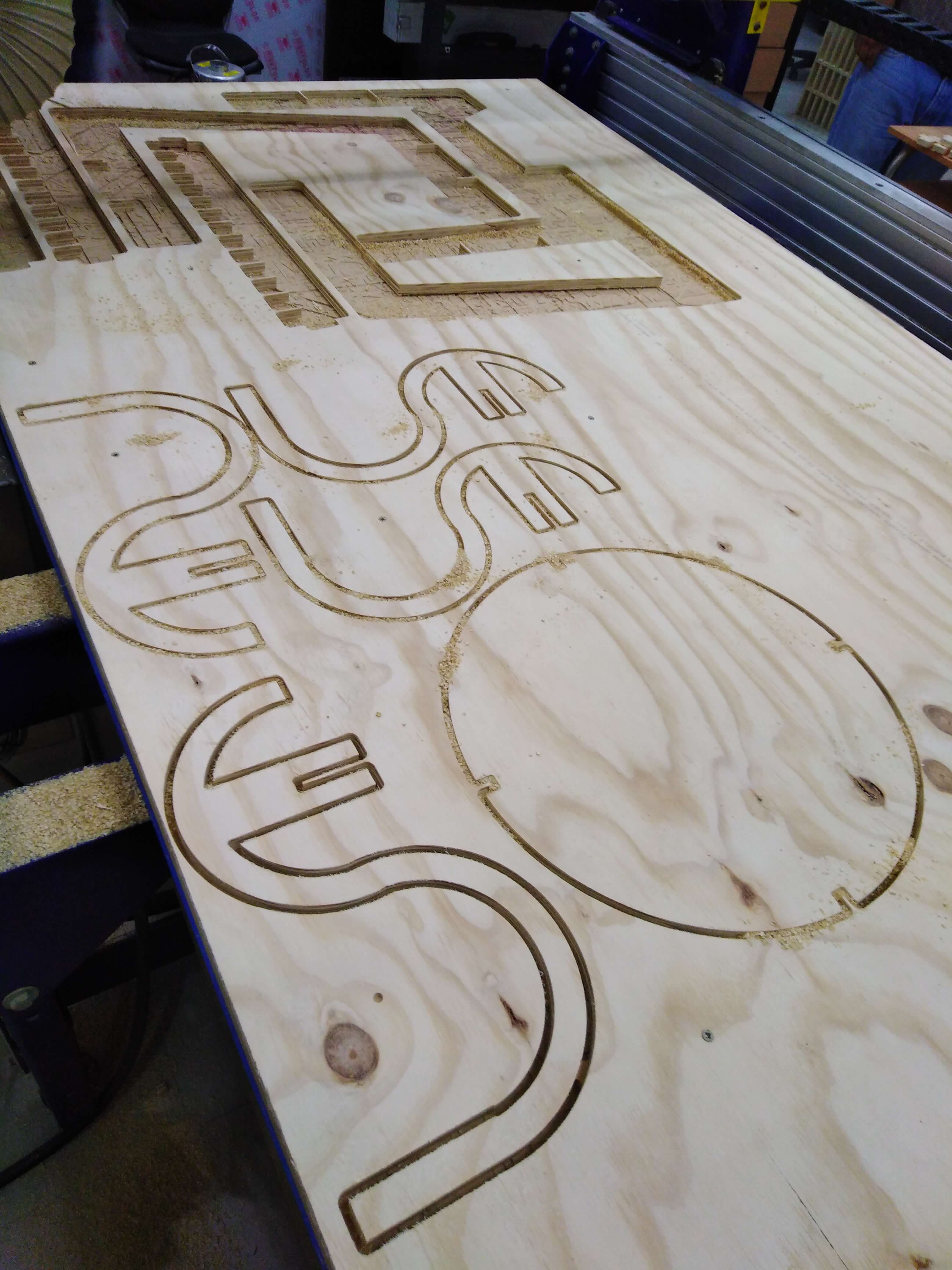
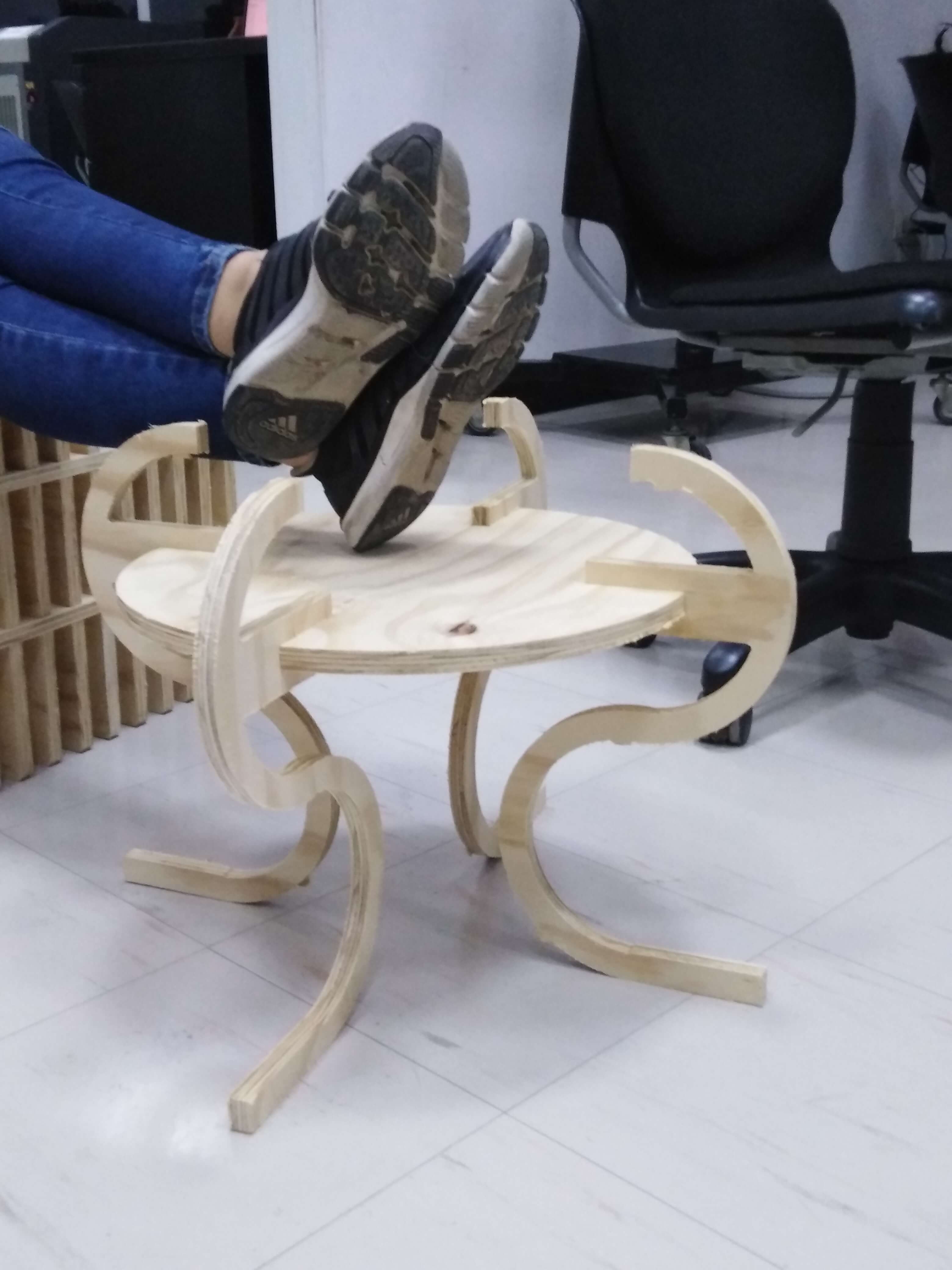
Finally the cut begins, and then just have to assemble the pieces and see the results...

Asignment goals
- Test runout, alignment, speeds, feeds, and toolpaths for your machine (Group assignment).
- Make something big on a CNC machine.
Download files: Press fit test
Download files: 3D FreeCad model Download files: DXF top view drawings
Learning outcomes
- Demonstrate 2D design development for CNC production.
- Describe workflows for CNC production.
Have you?
- Explained how you made your files for machining (2D or 3D).
- Shown how you made something BIG (setting up the machine, using fixings, testing joints, adjusting feeds and speeds, depth of cut etc).
- Described problems and how you fixed them.
- Included your design files and ‘hero shot’ photos of final object.